Categories
Microsoft Office Office 2016 Office 365 Visio Training

What’s new in Visio 2016
What’s new in Visio 2016

new-in-visio-2016
What’s new in Visio 2016

Believe it or not, Visio has been around for 20 years! Things have certainly moved on and improved since the first launch. Now, we are eagerly awaiting the release of Visio 2016. In this blog post, we shall be looking at what will be new in the next version.

Tell Me

The first new feature is found across the entire Office 2016 suite, namely the Tell Me bar in the ribbon. Here, users can type in search items or topics to quickly find features and methods to use in Visio 2016.

Tell me
What’s new in Visio 2016

There are a few improvements on already great tools found in the 2013 version of Visio. The first of these is improved shapes. Changes have been made to the following stencils:

  • Organisation chart
  • Network
  • UML
  • Database
  • Workflow and Sharepoint Workflow
  • Timeline
  • Basic Shapes

Themes

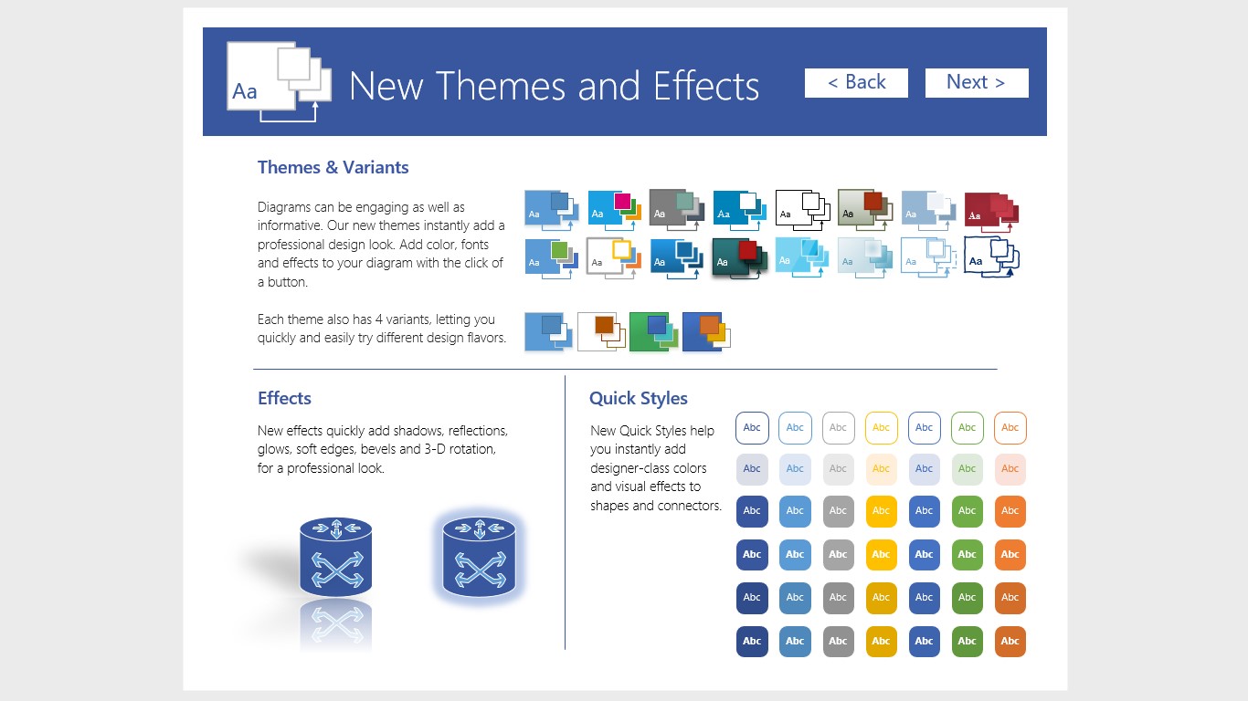
Next, updates have been applied to themes and shape effects, while a new feature has been made available, namely Quick Styles, which enables the user to give shapes a more professional look.
New Themes
What’s new in Visio 2016

Co-Authoring

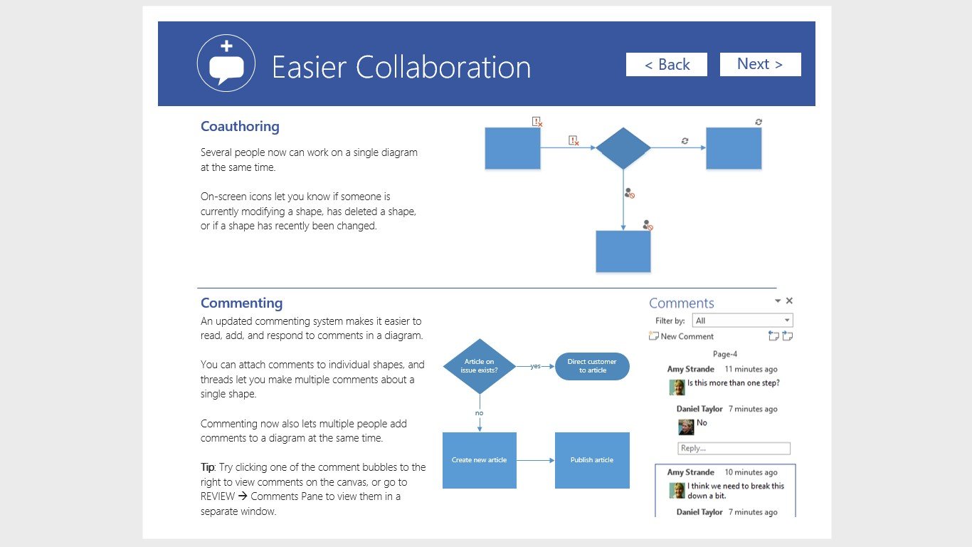
Thirdly, co-authoring allows more than one user to work on a drawing at the same time. On-screen icons show you when someone else is making changes to a drawing. Commenting has also been updated. Comments can be made on individual items and threads let you make multiple comments about a particular shape.
Collaboration
What’s new in Visio 2016

Content refresh in Visio

The Building Plan and Electrical stencils have been refreshed with new shapes so you have more variety to choose from.

Keyboard access for Shape Panel in Visio

Now enjoy easy access to the Visio Shape Panel using your keyboard. F6 cycles into the shape panel, TAB cycles through the different sections of the shape panel. Arrow keys allow users to navigate between the individual elements. Ctrl + TAB will allow users to quickly switch between STENCILS and SEARCH views.

Quick data linking in Visio

You can link a Visio diagram to Excel data, and then transform your diagram into a dynamic dashboard.

Information Rights Management (IRM) protection now added for Visio files

Visio files now offers Information Rights Management (IRM) features, which provide persistent online and offline protection of e-mail messages and attachments, documents and diagrams. Now you can protect sensitive information such as confidential product information, financial and sales process visuals, research and patent information and customer or employee data that live in Visio diagrams. Because people can now access their files from just about anywhere, large amounts of potentially sensitive information can suffer from information leakage can be a serious threat to organizations. To help prevent information leakage, protect your Visio diagrams with the new Information Rights Management (IRM) features.


Categories
Visio Training

List of Microsoft Visio Common Shapes and their Usage

When you open the Basic Flowchart template in Visio, the Basic Flowchart Shapes stencil opens too. Each shape on the stencil represents a different kind of step in a process. However, there is no standard, universal meaning for the shapes – any shape can carry whatever meaning is agreed on by the people who will create and read the flowcharts. Most flowcharts tend to use only three or four of the shapes, unless there is a clear business reason to use more.

Visio shapes generally have names that suggest their most common uses such as:

* Start/End: Use this shape for the first and last step of your process. Also known as a terminator.

Start / End

* Process: This shape represents a typical step in your process. This is the most frequently used shape in almost every process.

Process

* Decision: This shape indicates a point where the outcome of a decision dictates the next step. There can be multiple outcomes, but often there are just two — yes and no.

Decision

* Sub Process: Use this shape for a set of steps that combine to create a sub-process that is defined elsewhere, often on another page of the same document. This is useful if the diagram is very long and complex.

Sub Process

* Document: This shape represents a step that results in a document.

Document

* Data: This shape indicates that information is coming into the process from outside, or leaving the process. This shape can also be used to represent materials and is sometimes called an Input/Output shape.

Data

* On-page reference: This small circle (also known as Connector) indicates that the next (or previous) step is somewhere else on the drawing. This is particularly useful for large flowcharts where you would otherwise have to use a long connector, which can be hard to follow.

On Page Reference

* Off-page reference: When you drop this shape onto your drawing page, a dialog box opens where you can create a set of hyperlinks between two pages of a flowchart or between a sub-process shape and a separate flowchart page that shows the steps in that sub-process.

Off Page reference

* Alternate Process: As the shape name suggests, this flowchart symbol is used when the process flow step is an alternate to the normal process step. Flow lines into an alternate process flow step are typically dashed.

Alternate Process

* Delay: The Delay flowchart symbol depicts any waiting period that is part of a process. Delay shapes are common in process mapping.

Delay

* Preparation: As the names states, any process step that is a Preparation process flow step, such as a set-up operation.

Preparation

* Document: The Document flowchart symbol is for a process step that produces a document.

Document 1

* Merge (Storage) Flowchart: Shows the merging of multiple processes or information into one. Process Mapping: commonly indicates storage of raw materials.

Merge

* Extract (Measurement) Flowchart: Shows when a process splits into parallel paths. Also commonly indicates a Measurement, with a capital ‘M’ inside the symbol. Process Mapping: commonly indicates storage of finished goods.

Extract

* Or The logical Or symbol shows when a process diverges – usually for more than 2 branches. When using this symbol, it is important to label the out-going flow lines to indicate the criteria to follow each branch.

Progressive

* Summing Junction: The logical Summing Junction flowchart shape is shows when multiple branches converge into a single process. The merge symbol is more common for this use, though. This symbol and the Or symbol are really more relevant in data processing flow diagrams than in process flowcharts.

Summing Junction

The Most Commonly used Flowchart Symbols

The majority of flowcharts rely on just a few of the process-related symbols to do all the heavy lifting: Start/End, Process, Decision, Document, and Connector. In fact, if you use other flowcharting shapes, many people won’t know what they are for, so you may want to add a symbol key (legend) to your flowchart.

Get Microsoft Visio training London and UK wide from Best STL.